Table of Content
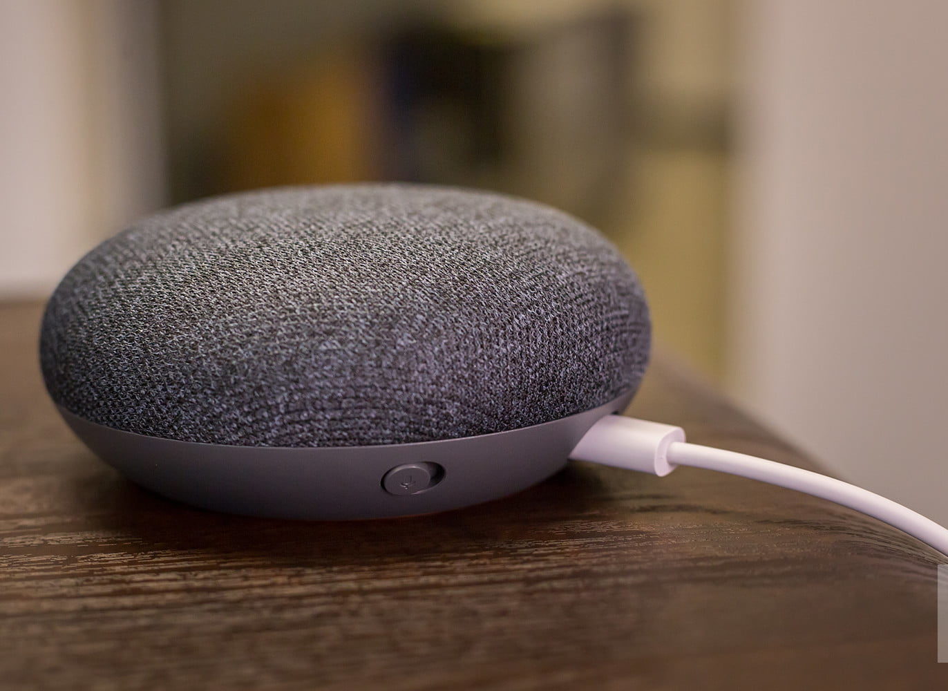
No neat smell from this air freshener unit , but we do find a "standby" button for Home's microphones, along with a status LED. Choose a size and copy the code below to embed this guide as a small widget on your site / forum. The Google Home Mini opens from the bottom There is an orange plastic disc with a piece of orange rubber attached to it. When autocomplete results are available use up and down arrows to review and enter to select. Touch device users, explore by touch or with swipe gestures.
The plastic is also used to electrically isolate two stainless steel “touch sensors” from the metal frame. These are used for sensing side-taps for volume control. Removing the hopefully final set of 4 torx screws, we set free the interesting metal/plastic part, and finally reveal the main PCB. Three more T6s secure a board bringing power input and a microphone switch down the ribbon cable.
Step 3
Grab the front of the speaker in one hand and the back cover in the other, and rotate the back clockwise slightly. The rubber insert comes out, revealing a sneaky T6 Torx screw. Insert an appropriate tool underneath this flexible rubber white insert. Many components are modular and can be replaced individually. But, from our multimetering, and reading of that final "-04", it looks to be a 4 ohm version.

The five screws securing this piece, which covers the logic board, are not. If you forget the positions, the picture has your back. Four more T6 screws secure the speaker assembly to the front. The DC-in port is soldered to the motherboard, but is unlikely to experience much wear, considering the device stays plugged in. The stretchy o-ring seems to be the key to delving even deeper inside this smart speaker. Removing the base gives us our first look at that high-excursion speaker and a hidden micro-USB debug/programming port.
Here’s The Hottest Look enlisted In The New VW Jetta
Using a pair of tweezers, unlatch the Zero Insertion Force fastener that connects the ribbon cable to the board. Be careful as a black ribbon cable connects the two halves together. Only standard screws and connectors are used throughout the device.
Also included is some Marvell switched-mode power supplies. There are also now only 4 RGB status LEDs, compared to the 12 in the original Google Home, and so they also got away with using only one LED driver, the NXP PCA9956BTW, instead of two. Ah, the pretty, soft-touch, and expressively-colored base-plate. Relieved of its T6s, the last piece pulls away with a bit of thermal shmoo.
Speaker
These changeable imprints are built into the tools so that one can easily and reliably track parts that are made. Note the overmolded metal part has a resolution of down to the day (day 2 & 3 of week 33) corresponding to what I believe is the 14 & 15th August. The plastic overmolding however indicates the 13th August. Is there something I am missing, or did tight production schedules require time travel? It also looks like the white plastic base was manufactured a month later, in September, likely due to the stricter cosmetic requirement meaning it was iterated on during validation runs more than internal parts.
And as with most MEMS microphones used today, the port is on the bottom, requiring a hole through the PCB, as can be seen below. Removing the black enclosure, we can see it is indeed an impressively sized custom speaker enclosure, and we get a hint at the solution to providing omnidirectional sound from the metal shape below. Donut try this at home 🍩About 5 minutes later, the base had softened and could be peeled right off, revealing the once stubborn double-sided adhesive that was similarily used in the original Google Home to attach the touchscreen. Google just announced some new products — one of which was the Google Home Mini, a smaller, cheaper version of their voice assistant, which just started shipping.
This smart speaker differs from its more diminutive sibling predominantly in its transducer allotment. TheGoogle Terms of Serviceand supplementalNest Terms of Serviceapply to use of the Google Home app and devices set up via the app. When available, your speaker or display will automatically update to the latest software version. The smaller version of Google Home voice-activated speaker, equipped with Google Assistant.
To get to the brains of the PCB, we’ll need to remove the metal shielding in 3 places. These typically consist of a “fence” that is soldered onto the board, and covers that can pop-off easily thanks to the little bumps along their perimeter. These little shields are very cheaply made from stamped sheet metal.
According to iFixit, getting to it is near-impossible due to the hefty, robust dollop of adhesive between it and the enclosure. So instead of redundantly tackling this same challenge myself, I’m going to “throw in the towel” and use iFixit’s images instead. Below are the specifications for Google Nest and Home speakers and displays . These are some common tools used to work on this device. Now lets take a look at the capacitive-touch volume controls, which did seem to be behaving.
I’m open to learn about how this compares in terms of time and cost on the assembly line. The flex cable connects to a small interfacing PCB, with a USB header, a toggle switch , and a reset button on the reverse, intended to be pressable through the baseplate. No other components here besides a decoupling capacitor for the 5V power supply. Overall, iFixit gave the speaker an 8 out of 10 on its own repairability scale, stating that it uses standard screws and connectors and that many of its parts are modular so they can be replaced quickly. The only low mark was given to the large amount of adhesive tape that was used to stick the touch board to the upper case of the Google Home.


No comments:
Post a Comment